Dynamics Lab
11.jpg?sfvrsn=aa5afb39_1)
Lab. Director: Dr. Bashmal Salem
Email: bashmal@kfupm.edu.sa
Lab. Engineer/Technician
Location: 63-237/239
Tel: (860- 3075)
Short introduction of the lab and its key capabilities/mission
The laboratory is fully equipped for performing vibration measurement, testing, and analysis, as well as dynamic controller design for both teaching and research purposes. Several hands on experiments related to vibration phenomenon and its measurements, as well as automatic control techniques are available for students and faculty.
Courses supported by Dynamics Lab are:
The Lab is used in teaching laboratory sessions of two ME core courses; ME-413 (System Dynamics & Control) and ME-482 (Mechanical Vibrations
Experiments related to M E 482: Mechanical Vibrations
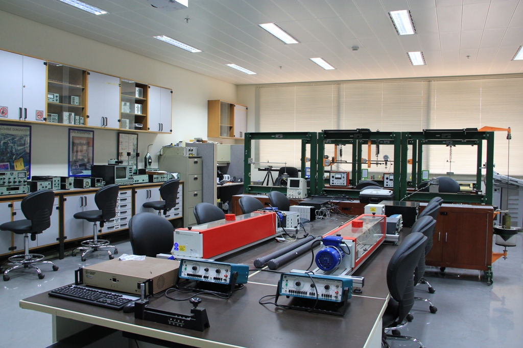
Vibration Lab
- The Simple Pendulum: The objectives of this experiment are: (i) to investigate the fundamental physical properties of a simple pendulum, (ii) to compare between experimental and theoretical periods of oscillations, (iii)to determine the acceleration due to gravity g using a simple pendulum
- The Compound Pendulum: The objectives of this experiment are to calculate the mass moment of inertia and radius of gyration of the compound pendulum of two bodies different in shapes and compare them to the theoretical values.
- Center of Percussion: The objectives of this experiment are: (i) to prove that the center of percussion of a compound pendulum is at a distance from the point of suspension equal to its equivalent length. i.e.; (ii) to compare the theoretical and experimental values of he radius of gyration
- Bifilar Pendulum: The objectives of this experiment are: (i) to determine experimentally the moment of inertia and radius of gyration of a rectangular bar, ring and cylinder, (ii) to compare the experimental results with the theoretical ones.
- Harmonic oscillations (spring mass system): The objectives of this experiment are: (i) to determine the stiffness of the spring by using three different methods: Analytically by using spring dimensions, by performing deflection measurements due to different loading conditions and by performing period measurements for different loading conditions. (ii) to determine the effective mass of the spring and (iii) to determine the gravitational acceleration (g).
- Torsional oscillations: The objectives of this experiment are: (i) to determine the modulus of rigidity G of an unknown material, (ii) to determine the m ass moment of inertia of a fly wheel using the Falling Weight Method (FWM), and (ii) to compare the experimental and theoretical periods for an oscillating flywheel.
- Free vibration with and without damping: The objectives of this experiment are: (i) to determine the viscous damping coefficient C as a function of the dashpot position in a certain dynamic system, and to learn how to estimate the dam ping coefficient C of a dynamic system experimentally.
- Forced vibration, with and without damping: The objectives of this experiment are: (i) to determine the natural frequency of a dynamic system using different methods, (ii) to determine the magnification factor ( ), and (iii) to plot the response curve of the dynamic system (Amplitude vs. excitation frequency).
- Undamped Dynamic Vibration Absorbers: The objectives of this experiment are: (i) to demonstrate how a tuned vibration absorber is used to eliminate the excessive vibrations of a single-degree-of-freedom system and (ii) to verify the validity of the absorber equations
- Whirling of Rotating Shafts: The objective of this experiment is to determine the fundamental frequency and the second frequency of a rotating shaft exhibiting whirling.
- Centrifugal Governors: The objectives of this experiment are: (i) to study the dynamic characteristics of a centrifugal governor and to determine its controlling force at various positions, and (ii) to compare the experimental and theoretical values.
- Lateral Vibration of Beams To Verify Dunkerley’s Rule: The objectives of this experiment are: (i) to determine the fundamental natural frequency of a rectangular beam experimentally using several attached masses and to compare the value obtained with the theoretical one, (ii) to determine the effective mass of a simply-supported beam experimentally and to com pare it with the theoretical value, (iii) to determine the stiffness of the beam experimentally and to compare it with the theoretical value, (iv) to demonstrate how Dunkerley’s equation can be used to determine the natural frequency of a lumped mass system attached to a beam and (v) to demonstrate how the Rayleigh’s method can be used to determine the natural frequency of a simply-supported beam .
Experiments related to M E 413: System Dynamics & Control
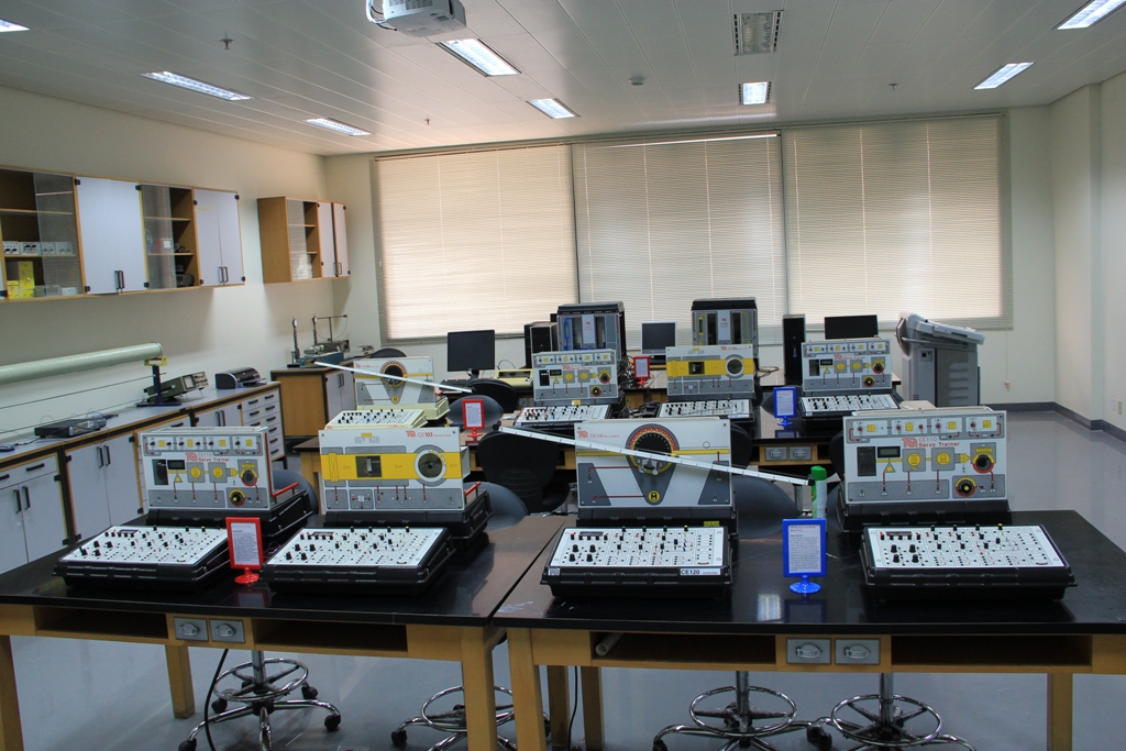
Control Lab
I. Apparatus: CE110 Servo Trainer and CE120 Controller
Range of Experiments:
- Basic Tests and Transducer Calibration: The objective of this experiment is to calibrate the circuits of the servo Trainer, namely the input actuator (the motor circuit) and also the output sensors (the speed and angular position sensors)
- Response Calculation & Measurements: The objective of this experiment is to determine the gain and the time constant of the servo-motor transfer functions with differing inertial loads.
- Proportional Control of Servo Trainer: The objective of this experiment is to implement a proportional controller of the Servo Trainer speed, study the transient response of the closed-loop system, and evaluate the steady state errors.
- Proportional plus Integral Control of Servo Trainer Speed: The objective of this experiment is to investigate the effect of proportional plus integral control upon the servo-motor speed control loop in terms of Steady state errors, disturbance rejection and transient response.
- Disturbance Cancellation and Feed-Forward Control: The objective of this experiment is to investigate the ability of a proportional, and proportional plus integral controller to reject disturbances caused by the load generator and to show how feed-forward control can assist in this respect.
- Angular Position Control: Proportional Control: The objective of this experiment is to investigate the angular position control performance and response of the Servo-Trainer under proportional control.
- Angular Position Control: Velocity feedback: The objective of this experiment is to investigate the use of velocity feedback as a means of improving the transient response of an angular position control system.
- Angular Position Control and The Influence of Nonlinearity: The objective of this experiment is to illustrate the practical effects of non¬linearity upon the performance of a position control Servo-Trainer using non-linear blocks provided.
- Non-linear System Characteristics: The objective of this experiment is to examine the characteristics of the non-linear elements and to investigate their influence upon typical signals.
Range of Experiments:
- Basic Tests and Transducer Calibration: The objective of this experiment is to calibrate the circuits of the Coupled Tanks Apparatus, namely the input actuator (the pump circuit) and also the output sensors (the flow rate and liquid level sensors).
- Open and Closed Loop Systems: The objectives of this experiment are (i) to investigate and com pare the performance and disturbance compensation capabilities of open-loop and closed-loop systems, (ii)to introduce the concepts of fluid level control using two term control or Proportional plus Integral(PI) Control.
- PI Controller Tuning 1; Hand Tuning of a single Tank: The objective of this experiment is to investigate the steady-state error and the step response properties of a PI-Controller applied to a single tank system and study the factors involved in tuning a PI-Controller manually.
- PI Controller Tuning 2; Hand Tuning of a double Tank: The objective of this experiment is to investigate the manual tuning of a PI-Controller applied to the level control of the second tank and explore the physical limitations of feedback control action.
- Measurement of System Response Characteristics: The objective of this experiment is to practically investigate the single tank response and hence determine the system gain and time constant.
- PI Controllers Tuning 3; The Single Tank System by damping factor and Bandwidth Specifications: The objective of this experiment is to tune a PI Controller for the single tank system to give a specified system bandwidth and damping factor using the gain and time constant measured in Experiment 5.
- PI Controllers Tuning 4; The double Tank System by Ziegler Nichol’s: The objective of this experiment is to measure the open-loop step response of the double tank system and hence design a PI controller using Ziegler-Nichol’s second method.
- Level Control Using State Feedback: The objective of this experiment is to use feedback of the liquid level in the first tank to modify the performance of the level controller for tank 2.
- Correcting for Phase Lag in Control Circuits: The objective of this experiment is to investigate the effect of phase lag elements in control circuits and practical remedies of such an effect.
- Multi-Variable PI control: The objective of this experiment is to place the Multi-Variable Coupled Tanks under PI control, such that the level in each tank can be independently controlled.
III. Apparatus: CE106 Ball and Beam and CE120 Controller
Range of Experiments:
- Basic Tests and Familiarization: The objective oft his experiment is to test basic functions of the apparatus, familiarize the user with the Ball and Beam apparatus and to calibrate the transducers (or sensors), namely the beam angle transducer and the ball position transducers.
- Proportional Control of Beam Angle and Manual Control of Ball Position: The objective of this experiment is to place the beam angle under closed loop proportional control and illustrate the difficulty of manually controlling the ball position.
- Phase Advance Control of Ball Position: The objective of this experiment is to place the ball position under phase advance control using the advance block on the CE120 controller, and to illustrate pre¬-filtering of the reference signal.
- Proportional Plus Derivative Control of Ball Position: The objective of this experiment is to place the ball position under phase advance control using proportional plus derivative (PD) blocks of the PID controller on the CE120 controller, and to illustrating high frequency filtering in the feedback loop.
- Measurement of System Characteristics and Alternative PD Design: The objective of this experiment is to measure the ball and beam transfer function and hence design the coefficients of a PD controller using an alternative PD implementation.
IV. Apparatus: CE103 Thermal Process Control and CE120 Controller
Range of Experiments:
- Basic Tests and Familiarization: The objective oft his experiment is to test basic functions of the apparatus, familiarize the user with various controllers and outputs of the Thermal Process Control Apparatus; e.g. heater, fan & shutter, and temperature sensor characteristics.
- On-Off Control: The objective of this experiment is to investigate the On-Off control using the relay amplifier on the front panel.
- On-Off Control with Hysteresis: The objective of this experiment is to investigate the performance of On-Off control with hysteresis using the relay amplifier provided.
- Proportional Control: The objective of this experiment is to practically investigate the performance of thermal control system under proportional control.
- Proportional plus Integral Control: The objective of this experiment is to practically investigate the addition of integral action to the thermal proportional controller.
- Feedforward Control: The objective of this experiment is to practically investigate the addition of feedforward control action to compensate for disturbances introduced by varying the shutter opening.
Laboratory equipment dedicated to teaching only
- Torsional Vibration Apparatus TQ, (3 sets)
- Beam Vibration Apparatus, TQ (3 sets)
- Servo Trainer Apparatus TQ, (4 set)
- Coupled Tank Apparatus TQ, (2 sets)
- Ball & Beam Apparatus TQ, (2 set)
- Thermal Process Control Apparatus TQ, (2 set)
- Cam & Follower HTM8, TQ, (2 sets)
Experimental setups used for teaching
Bently Nevada Rotor Kit .
2- B&K Type 3906 Medium-size Balancing Machine.
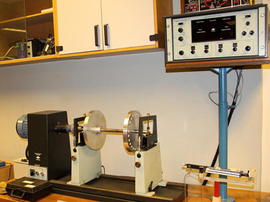
(balancing machine)
Test-benches used for research
Summary of the research you/others are undertaking
A rotating drillstring test rig. A flexible in-house manufactured test rig, which is well instrumented for carrying out vibration analysis of rotating Drillstrings, stick slip phenomenon in drilling, drilling fluid interaction, etc.
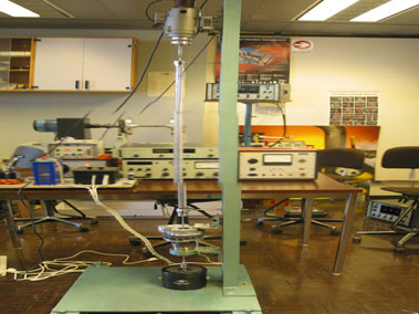
(Drilling test rig)
- A Multi-disk, multi-bearing flexible rotor test rig. Versatile setup for using different types/number of bearings, bearing location and shaft diameters, which is driven by high-speed motor (10,000rpm). Instrumented with proximity probes and accelerometers. The setup is capable of conducting vibration analysis of hig-speed supercritical rotors.
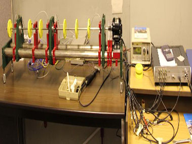
(High-speed multi-disk rotor)
Major Supporting Hardware
- B&K PULSE data acquisition and modal analysis System
- LabView Data acquisition and Control Systems (6 sets)
- AMETRON Laser Doppler vibrometer
- Sound Level Meter B&K Type 2231
- Frequency Analyzers B&K Types 2033, 2035
- Shakers, Amplifiers, Signal Generators, Oscilloscopes & Recorders
- An Array of Vibration Transducers.
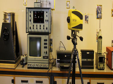
(Laser Vibrometer & Data acquisition systems)