Desalination Lab
1c017c4d-a497-43d7-9367-53930b51735d.jpg?sfvrsn=8f4c3f4d_1)
Short introduction of the lab and its key capabilities/mission
Setups
- Humidification dehumidification setup integrated to a heat pump
Description:
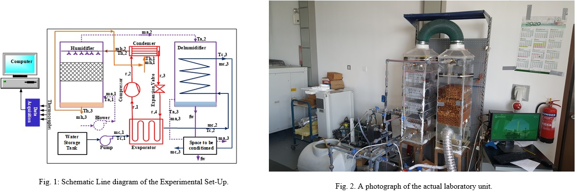
The schematic representation of the experimental set-up and process for the proposed integrated HDH desalination unit and heat pump is presented in the Figures. The desalination unit comprises two cycles namely: HDH cycle and heat pump cycle. The HDH cycle contains two main components (Humidifier and Dehumidifier), while the heat pump cycle entails condenser, evaporator, compressor and throttling valve. The hot saline water exiting the condenser of heat pump is sprayed in the humidifier over the packing material. A portion of the hot saline water is evaporated and carried by the incoming air, while un-evaporated saline water is rejected at the bottom of the humidifier as brine. A part of the discharged brine may be recycled through the condenser of heat pump depending on the desire water inlet temperature to the condenser of the heat pump. The saturated air leaving the humidifier is directed to the dehumidifier, where the vapor content in the air is condensed (air is dehumidified) as a result of chilled water flowing through the heat exchangers of the dehumidifier. The condensed vapor is collected at the bottom of the dehumidifier as distillate (freshwater), while the low temperature dehumidified air leaving the dehumidifier may be used for space cooling. Effective dehumidification (vapor condensation) is achieved by pumping chilled water (water exiting the evaporator of heat pump) through the heat exchanger coil located in the dehumidifier. Hot saline water and chilled water are achieved by condensing and evaporating refrigerant in the condenser and evaporator of the heat pump, respectively. Therefore, the heat pump system is used to simultaneously provide the cooling demand in the dehumidifier and heating demand in the humidifier. Chilled water is attained when the supply water (usually at room temperature) transfer heat to the refrigerant in the evaporator, while hot saline water is achieved when refrigerant in the condenser transfers heat to the saline feed water at various temperatures. The HDH unit is operated at atmospheric condition (pressure is assumed to be 101.325 kPa).
Papers associated with this system
- Dahiru U. Lawal, Mohamed A. Antar, Atia Khalifa, Syed Zubair and Fahad Al-Sulaiman, Humidification-Dehumidification Desalination System Operated By a Heat Pump, Energy Conversion and Management, Volume 161, 1 April 2018, Pages 128-140.
- Dahiru U. Lawal, Syed. M. Zubair, M. A. Antar, Exergo-Economic Analysis of Humidification-Dehumidification (HDH) Desalination Systems Driven by Heat Pump (HP), Desalination, Volume 443, 1 October 2018, Pages 11–25
- Dahiru U. Lawal, Mohamed A. Antar, Atia Khalifa, Syed Zubair and Fahad Al-Sulaiman, Experımental Investıgatıon of Heat Pump Drıven Humıdıfıcatıon-Dehumıdıfıcatıon Desalınatıon System for Water Desalination and Space Conditioning, Desalination,Vol. 475, 114199, 2020.
- Dahiru U. Lawal, Mohamed A. Antar, Atia Khalifa, Syed Zubair, Heat Pump operated Humidification Dehumidification Desalination System with option of Energy Recovery, Separation Science and Technology, pp. 1-20, 2020.
- D. U. Lawal, M. A. Antar, A. E. Khalifa and Z. M. Zubair, "Experımental Investıgatıon of Heat Pump Drıven Humıdıfıcatıon-Dehumıdıfıcatıon Desalınatıon Unıt", IDA World Congress, Dubai, WTC 20-24 October, 2019.
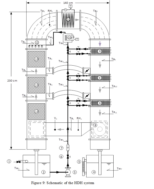
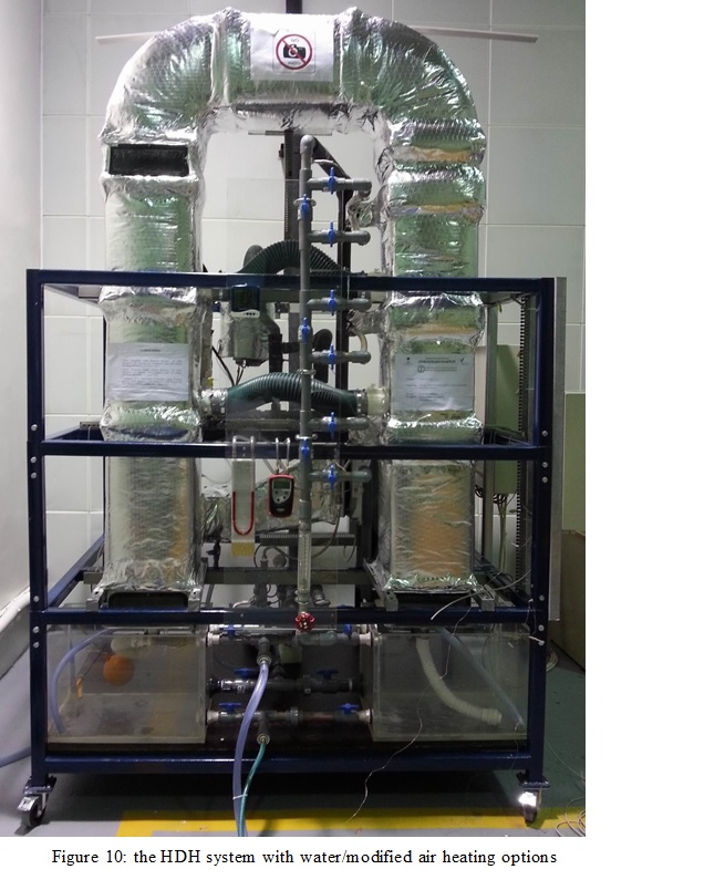
- Horizontal Flow Cross water heated HDH system


A photograph and a schematic of the designed, constructed and tested experimental lab-scale setup is depicted in figures. The humidifier and dehumidifier units are made of Plexiglas material, and in the form of horizontal rectangular ducts connected by U-pipe (6" PVC I) at one end. The humidifier has cross sectional dimensions of 30 cm x 30 cm and a length of 90 cm. Three structured-type packing-material of 15 cm thickness, separated by a distance of 10 cm are installed inside the humidifier. Mist eliminators are installed at the downstream of the humidifier to strip the water droplets that are carried by the humidified air. The dehumidifier has a height of 25 cm, width of 30 cm and a length of 110 cm. Three condensers made from copper tubes and aluminum fins are installed inside the dehumidifier for effective condensation of water vapor. Each of the three condensers has a thickness of 5 cm, separated by a distance of 30 cm. Air at room temperature is blown through the humidifier and passes through the packing material by an axial flow air blower installed at the humidifier entrance. The hot brackish water tank is fitted with two electric heaters with each having a heating capacity of 2 kW.
The hot water tank is insulated to reduce heat loss and ensure steady and constant temperature. Both hot and cold water were pumped through the humidifier and dehumidifier respectively using small centrifugal pumps, and ball valves are used to regulate the water flow rate. K-type thermocouples are installed at the inlet and outlet of the air and water streams to measure the dry bulb, wet bulb, and water temperatures. The thermocouple junction for the wet-bulb temperature measurement is wrapped by a wet wick supplied by water from a gravity feeding syringes. All the measuring sensors are connected to the National Instrument (NI) data acquisition system (IN cDAQ-9174 module) and all measured values are monitored and stored on a computer using a Labview code. Water flow rates are measured using In-line Flow meters glass tube rotameter (Omega FL46300) of ±5% accuracy and a range of 4-36 LPM. The air velocity is measured at the dehumidifier exit, and its measured using a digital anemometer (Smart Sensor AR 836) of ±3% accuracy. Pipes of 4 cm internal diameter located in-between the packing-materials and condensers are used for the mass extractions and injections from the humidifier to dehumidifier respectively.
Papers associated with this system
- A. Aburub, M. Aliyu, D. U. Lawal and M. A. Antar, "Experimental Investigations of the Performance of a Cross-Flow Humidification Dehumidification Desalination system" International Water Technology Journal, Vol. 7, No. 3, pp. 198-208, 2017.
- Dahiru U. Lawal, Mohamed A. Antar, Abdelrahman Aburub and Mansur Aliyu, "Performance Assessment of a Cross-Flow Packed-Bed Humidification-Dehumidification (HDH) Desalination system - The Effect of Mass Extraction", Desalination and Water Treatment, Vol. 104, pp. 28-37, 2018.
- HDH system with Counter-current flow in the Humidifier


In this arrangement as illustrated in the Figure, saline water enters the dehumidifier as cooling water and warms up before it is heated in a water heater or solar collector. The heated water is then sprayed in the humidifier which has a packing material to increase the heat and mass transfer area that enhances the evaporation process, the remaining unevaporated brine is rejected. The air loop in this cycle is closed. It enters the humidifier with a low humidity and leaves as hot and humid air. Thereafter, it enters the dehumidifier where it undergoes a cooling and dehumidifying process. The condensate water is then collected as a fresh water at the bottom of the dehumidifier and the air is circulated back to the humidifier to close the loop. In the case of single extraction, some of the air is extracted from the humidifier and injected into the dehumidifier by simply opening the valve, as shown in Fig.1, while the double extractions are illustrated in Figure 6 where there are two valves.
Papers associated with this system
- S. El-Mutasim, M. A. Mahmoud, M. A. Antar, S. M. Zubair, P. Gandhidasan, Design strategies of conventional and modified closed-air open-water humidification dehumidification systems, Desalination, Volume 435, 1 June 2018, Pages 114-127.
- S. M. Zubair, M, A. Antar, S El-Mutasim and Dahiru U. Lawal, Performance evaluation of humidification-dehumidification (HDH) desalination systems with and without heat recovery options: an experimental and theoretical investigation, Desalination, Desalination 436 (2018) 161–175.
- Bubble Column HDH system


The HDH system used consists of three stages: humidification, heating, and dehumidification. Bubbles column units are used for both HDH processes to increase the rate of heat and mass transfer between air and water, which would result in more effective evaporation and condensation. The schematic diagram of the bubble column HDH system is shown in Figures 7, 8. For the water heater system, air is flowing from a compressor through hot seawater in a bubble column humidifier where a perforated plate generates air bubbles. As air bubbles rise in the humidifier, air is heated and humidified. Warm humid air leaves the humidifier at the top. On the other hand, for the air heated system, air flows from a compressor to a cylindrical air heater, where its temperature is controlled using a thermostat. Then, hot air enters the humidifier from the bottom through the perforated plate where it is humidified and slightly cooled. In the bubble column dehumidifier, humid air is injected through cold freshwater. The freshwater may be cooled by a heat exchange coil connected to a chiller to keep the water temperature in the dehumidifier low to improve the condensation of moist air. As humid air rises as bubbles, water vapor carried by the air condenses and increases the level of freshwater in the dehumidifier.
Papers associated with this system
- B. A. Abdelkader, M. Khan, M. A. Antar and A. E. Khalifa, "Performance of Bubble Column Humidification-Dehumidification (HDH) Desalination System", Desalination and Water Treatment, Vol. 181, pp. 101-112, 2020.
- Submitted paper(s)
- Water heated and Air Heated HDH systems
A laboratory scale test rig was designed and built to investigate water-heated, air-heated, and balanced HDH cycles. Figure 1 illustrates a schematic diagram of the test rig used in the present work. The test rig mainly consist of packed bed humidifier on the left of the schematic, a finned tube dehumidifier on the right of the schematic, an electric air heater on the top (11), an electric water heater (10), a circulated air fan (8), a circulated water pump (3), float valve (1), sea water tank (2), distilled water tank (4), level indicator (5), valve(6), flow meter (7), water coil (heat exchanger) (9), sprinklers(12) and a packing material(13).
Air flows through the humidifier using an air fan (8) where it is heated and humidified. Three sections of constructed packing material (13) are installed inside the humidifier duct at equal separated spaces of 15 cm. The height of each packing is 30cm with a square cross sectional area of 30×30 cm2. It is humidified while passing through three separate polypropylene packing material pieces from Brentwood Industries (model number: CF1200 MA) (13). Air is heated by an air heater (11) after which air is dehumidified inside the dehumidifier passing over three cooling coils (heat exchangers) (9) cooled by water, the distilled water container (4) has been designed to collect the water condensed from the dehumidifier. The set-up is designed for either air or water heated operation. Water is pumped from the sea water container (2) by the pump (3) passing through main valve (6) to control the flow then through in line flow meter used in a range of 0.3 to 5 GPM flowmeter made by omega (model number: FL46305) (7) to measure its flow rate by sending a signal to the data logger system, which uses 6 slots with ATA flash memory drive that includes 128 Mb memory card made by Fluke ( model number: FL46305). After that, water enters the cooling coils (9) to absorb the air heat resulting in dehumidifying the air, in the case of water heated cycle, water is heated in the water heater (10) then it is sprayed in the humidifier through the sprinklers (12), part of this sprayed water evaporates in the air whereas the rest is rejected to the sea water container (2) that is 140 cm wide made of galvanized mild steel sheets of 1 mm thickness, the three pieces of packing material are made of black PVC square cooling tower filling material with dimensions of (30×30×30) to enhance heat and mass transfer between the air and the water, the copper coils have a square dimensions of (30.4×30.4
) and the pipe diameter of (0.635cm), with height of (15.24 cm).
The dry bulb temperatures measured by standard K-type thermocouples which in the form of quick connect Thermocouple probes with miniature connectors made by omega (model number: KMQSS-125G-6) used in the experimental setup for measuring temperature along the air path at different points showed in Figure 1 (Ta1, Ta2, Ta3, Ta4, Ta5, Ta6, Ta7, Ta8, Ta9, Ta10and Ta11). Ta7 is the outlet temperature of air for the humidifier, Ta1 is the outlet temperature of air for the dehumidifier. The air flow rate is controlled manually by electric key and the velocity (Va) of the air is measured by a hot wire Anemometer with real time data logger made by omega (model number: HHF-SD1) after the air fan. RH1 and RH7 are the relative humilities at the inlet and outlet of the humidifier respectively, they is measured by relative humidity/temperature transmitter (RH and T probes), duct style made by Omega (model number: HX94V). The water temperatures are measured by standard K-type thermocouples in a rugged pipe plug thermocouple probe with 1/4 or 1/8 NPT fitting made by Omega (model number: TC-K-NPT-G-72-SMP) at different points showed in Figure 1 (Tw1, Tw2, Tw3, Tw4, Tw5, Tw6, and Tw7). Tw1 is water temperature after the main valve (Tw2, Tw3, and Tw4) are the water temperatures after the cooling coils, Tw5 is the water temperature after the water heater, (Tw6 andTw7) are the water temperatures in the sea water container and the distilled water container respectively.
Papers associated with this system
Submitted paper / and papers under preparation.
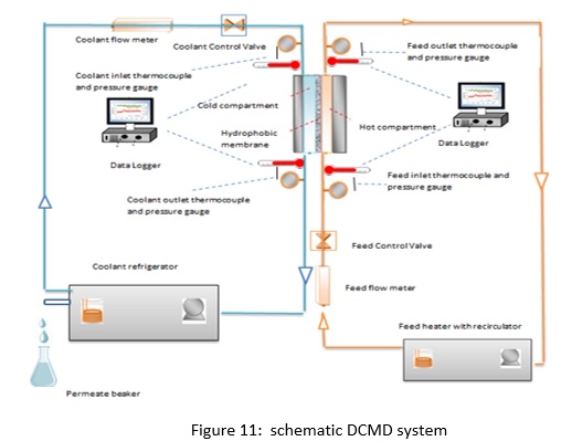
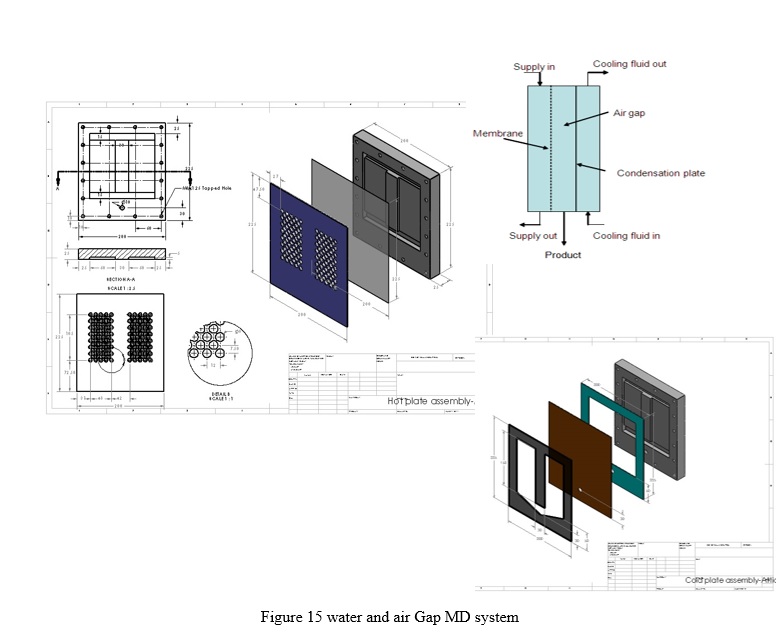
- Membrane Distillation system(s) built by Dr. Atia Khalifa

Papers associated with these systems
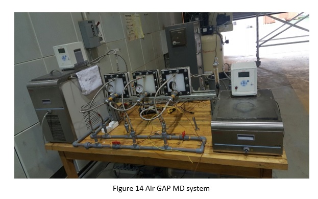
- A. Khalifa, D. U. Lawal and M. A. Antar, "Performance of Air Gap Membrane Distillation Unit for Water Desalination" Proceedings, IMECE 2014, Montreal Canada, November 14-20.
- A. Khalifa, D. Lawal, M. Antar and M. Khayet, "Experimental and theoretical investigation on water desalination using air gap membrane distillation", Desalination, Volume 376, Pages 94–108, November, 2015.
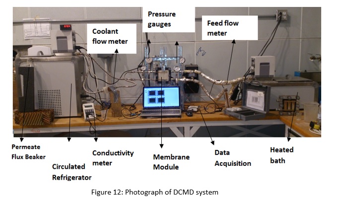
- H. M. Ahmad, A. Khalifa and M. A. Antar, "Water Desalination Using Direct Contact Membrane Distillation System", Proceedings of ASME 2015 International Mechanical Engineering Congress & Exposition, November 2015, Houston, USA.
- Atia Khalifa, Suhaib M. Alawad and Mohamed Antar, Parallel and Series Multistage Air Gap Membrane Distillation, Desalination, Vol. 417, pp. 69-76, 2017.
- Khalifa, H. Ahmad, M. A. Antar, T. Laoui, M. Khayet, Experimental and Theoretical investigations on Water Desalination Using Direct Contact Membrane Distillation", Desalination, Vol. 404, pp. 22-34, February, 2017.